Mushroom HVAC Control Priorities for the Global Market
Quick Answer

When a mushroom room calls for cooling and humidification at the same time, the controller should not simply switch every requested device on. It should first determine which environmental condition has priority, check whether outdoor air can help, and then sequence fans, dampers, cooling equipment and humidification so that one action does not cancel another. In many growing stages, preserving the crop’s required humidity while removing excess heat and carbon dioxide is the practical objective. The exact sequence, however, depends on the species, crop stage, room design, outdoor conditions and equipment limits.
A reliable mushroom HVAC sequence uses separate temperature, relative humidity and CO2 targets; defined operating priorities; minimum on/off times; and explicit interlocks. For example, a compressor may be held off while a damper is providing sufficient cool outdoor air, while humidification may be paused briefly during a high-airflow purge if the room is already near its humidity target. Such rules prevent unnecessary heating and cooling overlap, reduce short cycling, and make control behavior easier for operators to understand.
There is no single set of universal temperature, humidity or CO2 values suitable for every mushroom farm. Use crop-specific production guidance and confirm sensor locations, calibration and equipment capacity before commissioning. The goal is not to force all readings to their setpoints at once; it is to maintain an agreed operating envelope while protecting crop quality, energy use and equipment life.
Identify Simultaneous Cooling and Humidification Requests

Conflicting control requests often appear during rapid changes in crop activity or outdoor weather. The room may be warmer than its temperature target, so cooling is requested, while its relative humidity is below target, so humidification is requested as well. These conditions are not inherently contradictory: cooling can reduce air temperature while humidification adds moisture. They become problematic when the chosen cooling method, air exchange rate or control timing removes moisture faster than the humidifier can replace it, or when control loops continually counteract one another.
Begin diagnosis by separating a genuine load from a measurement or configuration problem. Confirm that the temperature and humidity sensors are calibrated, installed in representative locations, and shielded from direct mist, supply-air jets, radiant heat and condensation. Compare room readings with an independent handheld instrument. A sensor mounted beside a humidifier can report an artificially high humidity, while one close to a warm motor or light can overstate temperature. CO2 sensors also need appropriate placement and maintenance; readings near a fresh-air inlet may not represent the occupied crop zone.
Next, identify the operating mode and the source of each demand. Is the room in spawn run, pinning, fruiting or another defined stage? Is the temperature rise caused by crop respiration, lighting, equipment or warm outdoor air? Is humidity low because of excessive fresh-air exchange, a leaking room envelope, a low water supply, a clogged nozzle or insufficient humidification capacity? Record the sensor values, active outputs, outdoor conditions and controller mode together. A timestamped trend is more useful than a single snapshot because it reveals whether the demands are stable, alternating or rapidly oscillating.
Check whether “cooling” means compressor cooling, evaporative cooling, chilled-water cooling, or simply increased outside air. Each method affects humidity differently. A compressor coil can remove moisture when its surface is below the air’s dew point, whereas outdoor-air ventilation may either add or remove moisture depending on outdoor conditions. Evaporative cooling can lower dry-bulb temperature while raising moisture content, but its performance depends on the entering air and system design. The controller should therefore use the actual equipment configuration and, where feasible, outdoor temperature and humidity—not just a generic cooling output.
| Check | What to observe | Why it matters | Practical response |
|---|---|---|---|
| Temperature sensor | Reading, location and calibration | A biased reading can trigger unnecessary cooling | Compare with a calibrated reference and review placement |
| Humidity sensor | Reading near mist, coils or supply air | Local wetting or airflow can distort relative humidity | Relocate or shield the sensor as appropriate |
| CO2 sensor | Trend and position in the room | Poor placement may cause excess or insufficient purging | Verify calibration and representative sampling |
| Outdoor conditions | Temperature and moisture conditions | Fresh air may help cooling but worsen humidity | Assess outdoor air before opening dampers |
| Humidification hardware | Water supply, nozzles and pump status | Low delivery can resemble a control conflict | Inspect filters, pressure, leaks and distribution |
| Cooling equipment | Coil, airflow, drain and compressor status | Faults can reduce capacity or cause over-drying | Check alarms, condensate drainage and service condition |
This table is a fault-finding guide, not a substitute for the equipment manufacturer’s service procedures or the farm’s crop-specific limits. Once the cause is understood, configure the control sequence to distinguish a real simultaneous demand from a sensor fault, equipment alarm or temporarily changing load.
Map Temperature, Humidity, and CO2 Control Priorities

Before programming outputs, define the control priorities with the grower and the project engineer. Temperature, humidity and CO2 are coupled, but they are not interchangeable. A room can meet its temperature target and still have an unsuitable CO2 level. It can meet a humidity target at one sensor and have poor moisture distribution elsewhere. A control strategy should state which condition has priority in each crop phase, what limits cannot be crossed, and what action is permitted when two demands compete.
A practical hierarchy often begins with life-safety and equipment protections, followed by crop-critical operating limits, then routine setpoint control and finally energy optimization. Within the crop-control layer, the farm may choose to give CO2 removal priority during a defined high-CO2 event, provided the resulting air exchange will not push temperature or humidity beyond agreed limits. Alternatively, a temperature limit may require immediate cooling, with humidity recovery handled afterward. The right choice must be agreed for the species, crop stage and production protocol; it should not be guessed by a programmer.
Use operating bands instead of treating every setpoint as an absolute, instantaneous command. Define a target and an acceptable range for each variable. Add high and low alarms that are distinct from ordinary control thresholds. Where the crop protocol calls for gradual transitions between stages, setpoints can be scheduled or changed through an operator-approved recipe. Avoid abrupt setpoint changes that cause large simultaneous calls from several loops.
| Variable | Typical control purpose | Potential interaction | Design consideration |
|---|---|---|---|
| Room temperature | Maintain the crop-stage thermal range | Cooling may dry air or trigger heating recovery | Use a documented band and minimum equipment times |
| Relative humidity | Support the required crop environment | Ventilation and coil cooling can remove moisture | Locate sensors away from direct mist and drafts |
| CO2 concentration | Guide fresh-air exchange and crop-stage conditions | Purging may change heat and moisture loads | Use a suitable sensor and defined purge limits |
| Outdoor temperature | Assess free cooling potential | Outside air may create a heating demand | Apply outdoor-air enable and lockout conditions |
| Outdoor humidity or dew point | Estimate moisture impact of ventilation | Ventilation can humidify or dry the room | Consider moisture conditions, not temperature alone |
| Equipment status | Confirm available capacity and protect machinery | A failed device can invalidate the normal sequence | Use alarms, fallback modes and clear operator notices |
The table helps teams identify which measurements the controller should use. It does not prescribe universal crop setpoints. Mushroom varieties, substrate, room construction, air distribution and production stage differ, so the operating schedule should come from validated cultivation practice and be reviewed with the farm’s technical team.
For CO2 control, decide whether the controller should modulate ventilation, operate it in stages, or initiate a timed purge. A fixed purge schedule may be simple, but it can waste energy when conditions do not require it. Demand-based ventilation can be more responsive, but only when sensors, dampers and minimum airflow are reliable. A robust strategy may combine a CO2 target band with a maximum purge duration, minimum interval between purges and temperature or humidity safeguards. If a safeguard limits ventilation, the system should indicate the constraint rather than silently masking the CO2 demand.
Define Interlocks Between Fans, Dampers, and Compressors
Interlocks prevent equipment from operating in combinations that are ineffective, damaging or contrary to the agreed sequence. They should be documented as clear conditions: what must be true before an output starts, what holds it off, what stops it, and what happens if proof of operation is missing. A fan command is not proof that the fan is running; use an appropriate status signal where the design provides one. Likewise, a damper command does not prove that the damper reached position.
For a system with an outdoor-air damper and mechanical cooling, an outdoor-air cooling stage may be enabled only when outside conditions are favorable, the room is above its cooling band and the damper and fan are available. Compressor cooling may be delayed while this stage operates, unless the room reaches a high-temperature limit or outdoor air cannot meet the load. If the compressor runs, the control sequence should establish the required airflow and verify applicable coil, drain and safety conditions. Exact wiring and equipment protections must follow the approved design and manufacturer instructions.
Humidification may need an airflow proof, water-pressure proof or other permissive depending on the equipment. It may be inhibited during a fault, a maintenance mode or a short period of intensive purge, but any inhibition should have a clear release condition. Do not create a sequence in which humidification is permanently blocked whenever ventilation operates; that could make humidity recovery impossible in a high-air-exchange room. Instead, use a defined priority, a recovery mode or a controlled limit on competing outputs.
| Output | Enable condition | Hold-off or stop condition | Verification |
|---|---|---|---|
| Supply fan | Room mode active and no protective fault | Emergency stop, maintenance lockout or approved fault | Run status, current or airflow proof where designed |
| Exhaust fan | CO2 demand or approved purge request | Minimum off time or safety condition | Fan status and room response trend |
| Outdoor-air damper | Ventilation demand and favorable enable conditions | Frost, adverse outdoor condition or fault limit | Position feedback or end switch where provided |
| Compressor | Cooling demand, airflow available and safeties healthy | Minimum off time, lockout or high/low pressure fault | Run status, alarm state and temperature trend |
| Humidifier | Humidity demand and required permissives present | High humidity, water fault or equipment lockout | Output status and measured humidity response |
| Heater | Heating demand and cooling outputs released as designed | Cooling call, high temperature or safety fault | Output status and temperature trend |
The interlocks shown are examples for discussion, not a wiring diagram. Some installations use separate supply and exhaust fans, heat recovery, chilled water, heat pumps or multiple conditioning zones. Engineers should adapt the logic to the actual equipment and confirm that fire, electrical, refrigerant and other applicable protections remain independent and effective.
Consider failure behavior explicitly. If a damper fails to open, should the compressor remain available? If the CO2 sensor fails, should ventilation fall back to a timed schedule, a safe fixed position or a manual operating mode? If a fan proof is lost, should humidification and compressor operation stop? The safe response depends on the design and risk assessment. Provide an alarm that tells the operator what failed and what the controller has done, rather than displaying only a generic “system fault.”
Prevent Unnecessary Heating and Cooling Overlap
Simultaneous heating and cooling can arise when separate control loops use different sensors, setpoints or response times. A cooling stage may remain active after the room has crossed its target, while a heating loop reacts to a nearby cold sensor. A reheat coil may also operate intentionally to control supply-air temperature or humidity; in that case, simultaneous cooling and heating can be part of a carefully designed process. The key is to distinguish an engineered, necessary sequence from accidental overlap.
Start with a clear deadband between heating and cooling. The deadband is the range in which neither mode is called. Its size should reflect room thermal inertia, sensor accuracy, equipment capacity and crop requirements. A very narrow band can cause frequent switching; a very wide band can allow excessive drift. Do not select a number solely because it is common in another building. Review trends after commissioning and adjust in measured steps.
Apply mutual exclusion where the system design requires it: for example, an active heating call may hold off compressor cooling, and an active cooling call may hold off a heater, except for explicitly authorized reheat or safety sequences. Add minimum run and minimum off times consistent with manufacturer requirements. Use an anti-short-cycle timer for compressors and avoid restarting equipment immediately after a power interruption. Where staged equipment is present, bring stages on and off in an orderly sequence rather than switching all capacity at once.
Review humidification and ventilation alongside heating and cooling. A high outside-air rate can create a heating load in cold weather, while reduced ventilation to conserve heat can allow CO2 to rise. Humidification may increase the moisture load on a cooling coil, and mechanical cooling may dehumidify the room. The controller should make these consequences visible in trends and operator screens. If the system has heat recovery, verify that it operates as intended and does not compromise the crop environment or required exhaust path.
Control hunting can be caused by excessive proportional gain, poorly tuned integral action, sensor lag, oversized equipment, poor air mixing or a sensor located too close to a supply outlet. Check these factors before widening setpoints to hide the symptom. In a multi-zone cultivation facility, confirm that one zone’s control action does not shift pressure or airflow enough to destabilize another zone. The correct fix may be balancing, sensor relocation, revised staging or equipment adjustment rather than a new setpoint.
Set Practical Deadbands and Time Delays
Deadbands and time delays provide stability, but they should be selected deliberately. A deadband prevents small variations around the target from repeatedly changing the output state. A time delay prevents a brief sensor fluctuation from starting equipment. Minimum run and off times protect compressors and other devices from rapid cycling. Ramp limits can soften large changes in damper position, fan speed or setpoint, provided the ramp does not obstruct a critical crop or safety response.
Choose each delay according to the equipment and the process. A compressor’s minimum off time must follow its manufacturer’s instructions. Fan delays may be used to establish airflow before enabling a coil, or to allow a controlled purge after another output stops. Humidifier delays should account for the time needed for moisture to mix before the controller judges the response; otherwise, the sensor may see a local change and stop the device too early. Conversely, an excessively long delay can cause overshoot or prolonged operation.
Document separate values for normal control, alarm thresholds and protective trips. Operators should know which limits generate a warning, which initiate a controlled response and which require equipment shutdown. Avoid changing a safety threshold merely to resolve a nuisance alarm. If alarms recur, identify the cause—sensor location, equipment capacity, airflow, drainage or control tuning—and correct it through an approved process.
| Parameter | Purpose | Selection basis | Review method |
|---|---|---|---|
| Temperature deadband | Reduce heat/cool mode switching | Crop range, sensor accuracy and room response | Trend temperature and output changes |
| Humidity deadband | Stabilize humidifier operation | Sensor performance and moisture mixing time | Compare distributed readings and output status |
| CO2 start/stop band | Avoid repeated short ventilation calls | Crop-stage targets and ventilation capacity | Review CO2 recovery after purge events |
| Compressor minimum off time | Limit short cycling and protect equipment | Manufacturer requirements and approved design | Verify event logs and compressor starts |
| Fan or damper delay | Sequence airflow and conditioning stages | System layout and measured response | Confirm status feedback and room response |
| Alarm persistence time | Filter brief disturbances without hiding faults | Process dynamics and alarm priority | Review alarm history with operators |
These parameters should be recorded in the commissioning file and in the operator-facing control description. A controller that allows authorized users to adjust recipes should also preserve the approved baseline, identify who changed a value and provide a straightforward way to restore a known configuration.
Test Control Sequences Under Competing Loads
Commissioning should test both ordinary operation and deliberately competing demands. Start with point-to-point checks: verify sensors, output commands, feedback signals, alarms and actuator direction. Then test each mode separately—heating, cooling, humidification, ventilation and any recovery or energy-saving mode—before testing combinations. Confirm that emergency and manufacturer protections are not bypassed during these tests.
Use a written test plan that describes the expected sequence, initial conditions, simulated demand, observed outputs, acceptable response and pass/fail criteria. If safe, simulate a cooling call and a humidity call together. Confirm that the intended equipment starts, conflicting outputs remain inhibited where required, and the operator display explains the active priority. Repeat with a CO2 purge demand, an unfavorable outdoor condition, a failed sensor signal and a loss of fan proof. Do not introduce real crop risk simply to test an extreme alarm; use approved simulation methods where available.
Test recovery as well as activation. After a purge, how quickly does the room return to its temperature and humidity bands? Does the humidifier restart at the correct point? Does the compressor wait through its required minimum off time? Does the damper close after the ventilation demand ends? Does a fault clear automatically, or require operator acknowledgement? These details often reveal problems that a basic start-up test misses.
Record trends at a useful interval and include room readings, outdoor conditions, setpoints, output commands, equipment proof and alarm states. A trend with only temperature cannot explain why the compressor started while a fan or damper was unavailable. Keep the original test results alongside revised settings so future service teams can distinguish the commissioned sequence from later adjustments.
For commercial projects, consider testing representative rooms with different orientations, insulation levels and crop loads. A single room may not reveal pressure imbalance or distribution problems in a larger facility. Test under realistic operating conditions when possible, and repeat seasonal checks when outdoor weather changes substantially. Farms near the humid coastal climate of Qingdao, the colder winter conditions around northern China, or the hot and dry conditions of inland regions may face very different ventilation and moisture demands. Similar climate differences apply globally, from tropical production zones to high-altitude and temperate regions.
Document the Agreed Operating Logic for Operators
Good documentation translates engineering logic into practical operating guidance. It should identify each control mode, the conditions that start and stop it, the priority rules, the delays and deadbands, and the operator action required when an alarm occurs. Include a simple sequence diagram or truth table where it clarifies the relationship between temperature, humidity, CO2, fans, dampers, compressors, heaters and humidifiers.
Provide operators with plain-language explanations of why two demands may be shown at once while only one output is active. For instance, the screen may show “cooling requested” and “humidity requested,” while a temporary ventilation priority delays compressor cooling. The interface should identify which condition is controlling the decision and when the delayed action is expected to resume. This transparency reduces manual overrides and unnecessary setpoint changes.
Keep an approved setpoint schedule by crop stage, but make clear who may edit it. Include the responsible person, revision date and reasons for changes. Define how to operate during sensor failure, water interruption, outdoor-air restriction, compressor fault and power recovery. Manual modes should be time-limited or clearly indicated and should not defeat essential protections. After a manual intervention, staff should restore automatic control and confirm the room returns to the approved sequence.
Train operators to recognize trends rather than respond to one isolated reading. A brief humidity dip after a purge may be expected, while a sustained decline with a continuously operating humidifier suggests a capacity, water-delivery or distribution issue. Repeated compressor starts may indicate a deadband or equipment problem. Rising CO2 despite a ventilation command may point to a damper, fan, sensor or airflow fault. A short troubleshooting guide can help staff gather useful information before calling a service provider.
Market, Products, Buying Advice, and Applications
Commercial mushroom cultivation is expanding across a range of climates and facility types. Buyers increasingly look for integrated systems that combine insulated rooms or modular containers with climate controllers, fans, dampers, cooling equipment and humidification. The market is not limited to one region: production projects can be found near major agricultural centers, food distribution networks and logistics hubs. For international projects, access to service, spare parts, commissioning support and shipping routes can matter as much as the headline equipment specification.
Global project teams may coordinate equipment through major trade and logistics centers such as Shanghai, Qingdao, Shenzhen, Rotterdam, Hamburg, Singapore and Dubai. These are examples of trade hubs, not a claim that every system ships through each location. Buyers should confirm the actual route, import requirements, local electrical standards, refrigerant regulations, customs documentation and availability of qualified installation support in the destination country. For projects in Europe, North America, Southeast Asia, the Middle East or Africa, local climate and compliance requirements should be reviewed before final design.
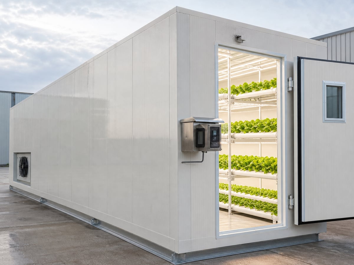
Common product approaches include a central HVAC system serving several rooms, dedicated equipment for each cultivation room, and modular cultivation containers with integrated climate control. A central plant may suit a larger facility with professional maintenance resources and coordinated room schedules. Dedicated systems can simplify independent operation but may increase the number of service points. A containerized solution can support phased deployment and site flexibility, provided transport access, foundation, electrical supply, drainage and maintenance clearances are planned.
| Configuration | Best-fit project consideration | Control benefit | Buying question |
|---|---|---|---|
| Dedicated room HVAC | Rooms with distinct crop schedules | Independent room-level control | Can each room be serviced without disrupting others? |
| Central plant with room terminals | Large facilities with shared engineering support | Centralized maintenance and capacity planning | How are zones balanced and isolated? |
| Integrated cultivation container | Phased or space-constrained production | Packaged climate functions and modular expansion | What site services and transport clearances are required? |
| Standalone climate controller | Retrofit or custom-built rooms | Coordinates existing compatible equipment | Which sensors, protocols and outputs are supported? |
| Heat-pump-based system | Projects seeking efficient heating and cooling options | Can serve multiple thermal needs where properly designed | What performance is expected at local outdoor conditions? |
| OEM or ODM system | Distributors and project integrators with defined requirements | Adaptation to project specifications and branding | What engineering documents and validation are included? |
Use this comparison as a starting point rather than a ranking. The right configuration depends on production scale, site utilities, climate, staff capability, redundancy requirements and expansion plans. Request a system narrative and equipment schedule so that a quotation can be compared on function rather than product names alone.
When evaluating a climate controller, ask how it handles simultaneous requests, sensor failures, outdoor-air limits, compressor delays, humidifier permissives and alarm priorities. Check whether the operator can view trends and output status, whether recipes can be managed by crop stage, and whether access can be restricted by user role. Confirm the supported voltage, communication interfaces, enclosure protection and environmental limits with the supplier. For facilities using multiple rooms, ask how the controller scales and whether data can be reviewed centrally.
For a complete project, inspect the room envelope and air distribution as carefully as the equipment list. Insulated panels, door seals, thermal bridges, drainage, condensate management and cleanable surfaces influence climate stability and hygiene. Confirm that supply air reaches the growing area without creating damaging local drafts or moisture gradients. Ask for stated performance assumptions, including outdoor design conditions, room heat load, ventilation rate and water quality requirements.
Potential applications include commercial button mushroom production, specialty mushroom rooms, research and demonstration facilities, agricultural training centers, food-sector pilot projects and modular cultivation programs. In each case, control logic should reflect the production process. A research room may require detailed data logging and tightly controlled experimental recipes, while a production farm may prioritize repeatability, clear alarms, fast maintenance and minimal downtime.
For instance, a farm operating several fruiting rooms may see one room require a CO2 purge while another needs temperature recovery. A properly zoned system prevents the first room’s ventilation demand from forcing an unnecessary change in the second. In a smaller container installation, a single controller may manage the major functions, but the operator still needs clear priorities and safe fallback behavior. These scenarios illustrate design considerations, not measured customer results or guarantees of a particular yield.
Buying advice should include the total operating picture. Compare energy use assumptions, maintenance intervals, filter and nozzle access, spare-part lead times, software support, commissioning scope and warranty terms. Ask who is responsible for installation, refrigerant work, water treatment, electrical connection and final control tuning. Clarify whether remote assistance is available, what data can be shared securely and how system settings are backed up. A low initial price may not represent the best value if the control sequence is unclear or service support is unavailable.
Local suppliers can provide advantages in site response, code familiarity and parts access. International manufacturers may offer integrated engineering, production capacity or customization. A project can use both, provided responsibilities are explicit: the equipment manufacturer should supply accurate technical information and the local contractor should confirm installation, commissioning and compliance. Buyers should request references relevant to similar climates and room scales, and verify claims through documentation rather than relying only on marketing language.
For international delivery, discuss packaging, corrosion protection, container loading, transport restraints and the handling of control panels or sensitive components. Confirm the shipping terms and identify who manages insurance, customs clearance and inland transport. A supplier’s ability to support factory testing, provide electrical diagrams and assist with installation guidance can reduce uncertainty, especially when the project team is distributed across countries.
Test and Improve the System Over Time
Control quality is not fixed at handover. Review system trends after a full operating period and compare them with crop outcomes, energy consumption, alarm frequency and operator feedback. A recurring conflict may indicate that the priority sequence is wrong, but it can also reveal undersized equipment, poor air distribution or changing production practices. Make changes through a controlled process: record the symptom, identify the likely cause, change one relevant parameter at a time and compare results under similar conditions.
Keep a maintenance plan for sensors, filters, coils, fans, dampers, pumps and humidification equipment. Calibration and inspection intervals should follow the device specifications and site experience. Dirty filters can reduce airflow and change coil behavior. Blocked nozzles can create uneven moisture distribution. A sticky damper may leave the controller believing that ventilation has stopped when it has not. Preventive maintenance protects both environmental control and the value of the equipment.
For larger farms, consider separating operator alerts from service alarms. An operator alert might explain that a target is temporarily unmet because a competing demand has priority. A service alarm may report that a compressor failed to start or a sensor signal is invalid. Clear categories help staff respond appropriately without normalizing serious faults. Review nuisance alarms periodically; too many unhelpful alerts can cause operators to overlook a meaningful one.
Future Trends for 2026 and Beyond
Climate-control projects are moving toward more connected monitoring, better data visibility and increased coordination between equipment. In 2026, buyers can expect growing interest in controllers that store room trends, support remote diagnostics and make operating states easier to compare across rooms. These capabilities can help teams identify recurring conflicts, but reliable sensors, cybersecurity practices and clear data ownership remain essential. A connected controller should not depend on an unstable network for basic local protection and control.
Smarter optimization may use weather forecasts, energy tariffs, room load patterns and equipment performance data to suggest when to use outdoor-air cooling or shift thermal loads. Such functions should remain bounded by crop-specific limits and transparent operator settings. Automated recommendations should be tested against actual farm conditions; an algorithm trained on a different climate, room geometry or crop schedule may make inappropriate decisions. Human review and a dependable fallback sequence remain important.
Sustainability is also shaping equipment choices. Efficient fans, well-insulated envelopes, heat recovery, properly selected heat pumps and reduced unnecessary ventilation can lower energy use when designed for the application. Water use, condensate management, refrigerant selection and equipment life should be considered alongside electricity consumption. Policy requirements vary by country and may change over time, so project teams should verify current building, electrical, refrigerant, environmental and import rules in the destination market rather than assume one global standard.
Future-ready systems should be modular enough to support expansion, but not so complex that operators cannot understand them. Open documentation, clear point lists and accessible trend exports can make future service easier. For farms comparing equipment, ask how the supplier handles software updates, backups, obsolete components and long-term spare parts. Sustainability gains are most credible when supported by measured operating data and a transparent calculation method.
Our Company
Shandong Lanhu Air Conditioning Equipment Co., Ltd. is based in Dezhou, Shandong, China, and develops agricultural climate-control equipment, industrial HVAC systems and modular cultivation solutions. Its product range includes smart mushroom cultivation containers, mushroom climate controllers, hydroponic plant containers and air-source heat pumps. For projects focused on coordinated room operation, buyers can review the company’s mushroom climate controller and discuss how the control sequence should handle competing temperature, humidity and CO2 demands.
Technological capabilities include more than 12 years of thermodynamic research and development experience and a portfolio of registered patents. The engineering team can work with project requirements for room climate, equipment integration and modular cultivation. A controller or packaged system should still be assessed against the actual crop protocol, site utilities and local installation conditions; buyers are encouraged to provide room dimensions, climate data, target operating stages and equipment preferences during technical discussions.
Manufacturing capabilities are supported by a production facility exceeding 30,000 square meters. The company’s integrated work includes product design, engineering development, sheet-metal fabrication, CNC bending, insulation-panel production, electrical assembly and system integration. Before shipment, equipment undergoes functional inspection, electrical verification, performance testing and operational evaluation. Its quality and management credentials include ISO 9001, ISO 14001, ISO 45001 and ISO 12100 certifications. For a modular project, explore the smart mushroom cultivation container and request the technical information needed to assess fit for the destination site.
Service capabilities include factory-direct supply, OEM and ODM customization, engineering assistance, international logistics support, spare parts support, installation guidance and after-sales service. The company works with agricultural contractors, equipment distributors, engineering companies and commercial farming projects worldwide. Buyers seeking a customized configuration can learn about OEM and ODM project support, including the information needed to define equipment scope and control functions.
When evaluating any supplier, ask for a clear sequence of operation, equipment schedule, test records and documentation in a form that the installation and operating teams can use. Discuss local compliance, service arrangements, commissioning responsibilities and spare-part planning before placing an order. To share project requirements or request a technical discussion, use the company’s contact page.
FAQ
Can cooling and humidification operate at the same time?
They can when the system is designed for simultaneous operation and the equipment can meet both loads. The controller should account for how cooling affects moisture and should prevent the humidifier from responding to a misleading local sensor reading. The agreed sequence may allow both outputs, stage one after the other, or temporarily prioritize one demand. Confirm the behavior through commissioning tests.
Should ventilation always take priority over temperature control?
No. The priority depends on crop stage, CO2 limits, room conditions, equipment capacity and the farm’s production protocol. A high CO2 event may require ventilation, but the sequence should consider the associated temperature and humidity effects. Document what happens when a protective limit restricts ventilation and provide an alarm or operator message.
Why does a room show a cooling request while the compressor is off?
The controller may be using an outdoor-air cooling stage, waiting through a minimum off time, observing a safety lockout or applying another agreed priority. The display should make the reason visible. If it does not, review the controller’s sequence description, output status and alarm history.
How can a farm reduce heating and cooling overlap?
Use a defined heating-cooling deadband, mutual exclusion where appropriate, manufacturer-compliant minimum times and coordinated sensor placement. Check whether any simultaneous operation is intentional, such as designed reheat. Trend the outputs and room readings before changing settings, because poor airflow or an oversized system may be the underlying cause.
Are the same setpoints suitable for all mushroom species and stages?
No. Required conditions vary by species, strain, crop stage, substrate, room design and production practice. Use validated crop guidance for the specific operation and have the control schedule reviewed by people responsible for cultivation and system engineering. A general HVAC article cannot replace a crop-specific operating protocol.
What should be included in an HVAC control handover?
Include the sequence of operation, sensor and output list, approved setpoints and limits, deadbands, time delays, alarm meanings, failure responses, trend instructions, maintenance guidance and operator training. Record software or configuration versions and retain commissioning results so future technicians can understand the original logic.
What information should buyers provide when requesting a quotation?
Provide room dimensions, insulation details, location and outdoor design conditions, crop stages, desired production schedule, available utilities, ventilation requirements and any existing equipment. Identify local electrical and regulatory requirements, shipping destination and preferred service arrangements. Clear information helps suppliers assess capacity and control scope more accurately.
Share this article

About the Author: Shandong Lanhu Air Conditioning Equipment
Lanhu is a professional climate control equipment manufacturer specializing in smart agricultural systems, commercial HVAC solutions, and customized temperature control technologies. With extensive engineering experience, Lanhu provides reliable solutions for plant factories, controlled environment agriculture, and industrial applications.
Need a Custom Climate Control Solution?
From smart agricultural systems to commercial HVAC solutions, Lanhu provides reliable temperature and humidity control solutions tailored to your project needs.
Contact Us